IN THE NEWS
Stay up to date on new products, recommended usage, and ongoing news in the field.

Stay up to date on new products, recommended usage, and ongoing news in the field.

Today, Ben McCawley gives the low-down on programming the EDI MMU2-16LEip.
Recently, a customer asked if a new MMU2-16LEip Conflict Monitor they received from the EDI factory will work directly out of the box when installed in a TS-2 cabinet?
That is a great question and the answer is “No, all monitors must be programmed for each cabinet.” If you leave it on the factory settings, it will do the conflicts and permissive, because that comes from the program card, but there are other parameters that you need to set. The wizard sets the Dual indication, Red Fail, Minimum Yellow and Red Clearance (MYRC) and Field Check. In the old monitors, we used dip switches to set these faults. You can also set these faults individually by doing it with the monitor menus, (Dual Ind, Red Fail, MYRC & Field Check), but the wizard makes it easier. Let me elaborate.
When I get questions like this, I have to ask some basic questions because I can’t assume anything. First, what cabinet architecture are you using? NEMA TS-1, TS-2, Caltrans, or the new Advanced Traffic Controller Cabinet (ATCC)? In this case, the customer was programming for the nearly 30-years old (1992) NEMA TS-2 standard and the monitor was an MMU2-16LEip.
When the MMU2-16LEip monitor comes from the factory the settings are defaulted to blank. You can verify this by looking at Field Check Enable, Dual Indication Enable, and Red Fail Enable; none are set. If you’re installing a monitor into an operational cabinet in the field, it’s best to check that monitor in a live cabinet in your shop before you put it into the field. You can do a pre-install check in a test cabinet or use a monitor power cord to set it up on your desk. For desktop testing see How to Make a Signal Monitor Bench Test Power Cable.
Programming
Power up the monitor and let’s get started.
How many phases are in your intersection? 2-phase, 4-phase, 8-phase, or more?
Do you have pedestrian phases and if so, are you going to monitor them?
Do you have left turn movements and if so, are they protected only, permissive only, or a combination of protected and permissive (PP-turn)?
The EDI MMU2-16LEip monitor has a Setup Wizard. However, the Setup Wizard does not configure the physical program card. You will need to manually configure the Program Card by adding jumpers to address Unit Data Permissive Matrix and Minimum Yellow Clearance Disable.
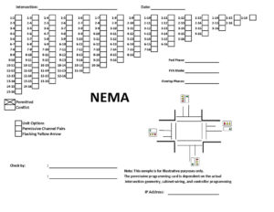 This is when I use the NEMA Program Card Worksheet that I have been using for 16 years. This form is a good checklist to ensure you do everything that the Setup Wizard does not do. I start by setting all of the Unit Options, such as Recurrent Pulse Monitoring, LED Guard, Log CVM Events, and others. It’s best if you fill out the Permissive and Conflict Matrix on this sheet, have it checked by a trained co-worker, and then transfer the configuration to jumpers on the program card. Since we are not using flashing yellow arrows at this intersection, we will proceed with running the Setup Wizard. See another Program Card Worksheet for Caltrans.
The built-in Setup Wizard is used to generate configuration values for the following parameters: Field Check Enable (Type 16 mode only), Red Fail Enable, Dual Indication Enable (RG, YG, and GY), and Minimum Yellow Plus Red Clearance.
There are two ways to get to the Setup Wizard from the Main Screen.
Menu Path: MENU / SETUP WIZARD
Menu Path: MENU / SET VIEW CONFIG / SETUP WIZARD
The built-in Setup Wizard configures the monitor’s Enhanced Features Programming using a series of intuitive intersection related questions. It allows a technician to accurately and completely program the monitor’s Enhanced Functions without the need for understanding the complexities of monitor Enhanced Configuration parameters. When programming, note that a channel is always labeled as “OTHER” in the Setup Wizard process until it has been assigned to an UNUSED, PED, VEH+PED, or PP-TURN function.
The first question in the Setup Wizard asks if there are any unused channels? This step selects the channels of the monitor that are not connected to a load switch, that is, unused. This selection can eliminate the need to connect the Red Input of an unused channel to AC+.
The NEXT button moves the ▼ symbol to the next channel number. The SELECT button will toggle from the OTHER state to the UNUSED state. A channel that is selected for UNUSED is indicated by the Red, Yellow, and Green icons being illuminated. A common question in this process asks, “Does designating a channel as UNUSED affect the Conflict programming on the Program Card? And the answer is, “No.”
When all UNUSED channels have been selected, the EXIT button will display the navigation choices of NEXT, CANCEL, and EDIT. The NEXT choice continues the Wizard operation with the next programming step. The CANCEL choice will exit from the Setup Wizard operation with no changes to the configuration data base. The EDIT choice will return to the Unused Channels step.
The second question in the Setup Wizard asks if there are Pedestrian Channels and if so, are they monitored? This step selects the channels of the Monitor that are connected to pedestrian load switches that drive the “Walk” and “Don’t Walk” signal displays. In NEMA TS-2, Type 16 mode, the Setup Wizard will ask if the “Don’t Walk” signal will be monitored? Answering “YES” will configure the Monitor to respond to a Red Fail or Dual Indication (R+G) fault if the “Don’t Walk” signal fails. In NEMA TS-1, Type 12 operation, this step is not required as the “Walk” input is programmed and assigned to the associated vehicle monitor channel (R, Y, G, W).
The NEXT button moves the ▼ symbol to the next channel number. The SELECT button will toggle from the OTHER state to the PED state. A channel that is selected for PED is indicated by “Walk” and Red icons are illuminated. When all PED channels have been selected, the EXIT button will display the navigation choices of NEXT, CANCEL, and EDIT. The NEXT choice continues the Setup Wizard operation with the next programming step. The CANCEL choice will exit from the Setup Wizard operation with no changes to the configuration data base. The EDIT choice will return to the Pedestrian Channels step.
The third question in the Setup Wizard asks about the left turn movements and if they are protected and/or permissive? This step selects the channels of the Monitor that are connected to a protected-permissive left turn channel load switch that drives only a Green and Yellow signal display. This selection can eliminate the need to connect the Red input of a protected-permissive turn channel to AC+. This selection can also include a right turn overlap that drives only a Green and Yellow signal display.
The NEXT button moves the ▼ symbol to the next channel number. The SELECT button will toggle from the OTHER state to the PP-TURN state. A channel that is selected for PP-TURN is indicated by the Green and Yellow icons illuminated. When all PP-TURN channels have been selected, the EXIT button will display the navigation choices of NEXT, CANCEL, and EDIT. The NEXT choice continues the Setup Wizard operation with the next programming step. The CANCEL choice will exit from the Setup Wizard operation with no changes to the configuration data base. The EDIT choice will return to the Protected-Permissive Turn Channels step.
At this point in the Setup Wizard, it is time to review your work by using the Channel Assignments screen. This step provides a review of all the channel assignments you selected in the previous steps. The NEXT button moves the ▼ symbol to the next channel number. All channels should be described as VEHICLE, UNUSED, PED, VEH+PED, or PP-TURN function. When all channels have been reviewed for correctness, and you have completed the configuration, the EXIT button will display the navigation choices of SET, CANCEL, and EDIT. The SET choice completes the Setup Wizard operation and sets the new configuration parameters. The CANCEL choice will exit from the Setup Wizard operation with no changes to the configuration data base. The EDIT choice will return to the first Setup Wizard step.
Once you finish with the Setup Wizard, the screen for New Parameter Settings appears. This is where you will configure for Dual Indication, Red Fail, and Minimum Yellow Red Clearance. It is necessary to take the time to review your settings. Some changes may need to made depending on the cabinet wiring or other considerations.
From start to finish, correctly programming the Monitor is a simple and intuitive process.
If you have a question you want answered please feel free to submit it to us.